1 Installation of ball valves
1.1 Ball valve installation before the preparation
(1) The pipeline before and after the ball valve is ready. Before and after the pipeline should be coaxial, the two flange sealing surface should be parallel. The pipeline should be able to bear the weight of the ball valve, otherwise the pipeline must be equipped with appropriate support. (2) Clean the pipeline before and after the valve and remove the oil, welding slag and all other impurities from the pipeline.
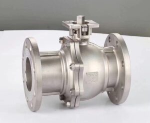
China Semi-ball Valve supplier
(3) Check the markings of the ball valve and make sure that the valve is intact. Fully open and close the valve several times to confirm that it works properly.
(4) Remove the protective parts on the connecting flanges at both ends of the ball valve.
(5) Check the valve hole to remove any dirt that may be present, and then clean the hole. Even only tiny particles of foreign matter between the valve seat and the ball may damage the sealing surface of the valve seat.
1.2 Ball valve installation
(1) Install the valve on the pipeline. Either end of the valve can be installed at the upstream end. Valves with handle actuation can be installed anywhere on the pipeline. However, ball valves with gearboxes or pneumatic actuators should be installed upright, i.e., on a horizontal pipeline with the actuator above the pipeline.
(2) The valve flange and the pipeline flange are fitted with gaskets according to the pipeline design requirements.
(3) The bolts on the flange need to be tightened symmetrically, one at a time, and evenly.
(4) Connect the pneumatic pipeline (when using pneumatic actuator).
1.3 Checking the ball valve after installation
(1) Operate the actuator to open and close the ball valve several times, and it should be flexible without stagnation to confirm its normal operation.
(2) Check the sealing performance of the flange joint surface between the pipeline and the ball valve according to the pipeline design requirements.
2 ball valve maintenance
2.1 The general rule of ball valve maintenance
(1) must first identify the ball valve upstream and downstream pipeline has been removed from the pressure, before disassembly decomposition operation.
(2) disassembly and reassembly must be careful to prevent damage to the sealing surface of the parts, especially non-metallic parts, to remove the O-ring should use special tools.
(3) The bolts on the flange must be tightened symmetrically, gradually and evenly when assembling.
(4) The cleaning agent should be compatible with the rubber parts, plastic parts, metal parts and working medium (such as gas) in the ball valve. When the working medium is gas, gasoline can be used to clean the metal parts. Non-metal parts are cleaned with pure water or alcohol.
(5) The decomposed individual parts can be cleaned by immersion. Still have not decomposed down the metal parts of the metal parts can be clean and fine impregnated with cleaning agent silk cloth (in order to avoid fiber off adhering to the parts) scrubbing. Cleaning must remove all adhering to the wall of grease, dirt, glue, dust, etc..
(6) non-metallic parts should be removed from the cleaning agent immediately after cleaning, and shall not be immersed for a long time.
(7) After cleaning, the wall cleaning agent should be washed after evaporation (can be wiped with a silk cloth not dipped in cleaning agent) for assembly, but shall not be set aside for a long time, otherwise it will rust and be contaminated by dust.
(8) New parts should also be cleaned before assembly.
(9) Use grease lubrication. Grease should be compatible with the ball valve metal materials, rubber parts, plastic parts and working medium are compatible. When the working medium is gas, use, for example, special 221 grease. Apply a thin layer of grease on the surface of the seal mounting groove, a thin layer of grease on the rubber seal, and a thin layer of grease on the sealing surface and friction surface of the valve stem.
(10) Assembly should not allow metal debris, fibers, grease (except those specified for use) dust and other impurities, foreign objects, etc. to contaminate, adhere to or remain on the surface of the parts or enter the inner cavity.
2.2 Online maintenance ball valve
Replacement of stem packing 40 or 45, O-rings 56 and 112, and external parts can be performed on the line without removing the valve from the line. There are different disassembly sequences for different actuators, as follows.
2.2.1 Ball Valves with Handles – Replacement of Packing 45
(1) Close the shut-off valves upstream and downstream of the ball valve. Bleed off the pressure in the pipeline before and after the ball valve.
(2) Keep the ball valve fully closed.
(3) Unscrew nut 52 and remove washer 75, wrench head 74, and handle 47.
(4) Unscrew nut 48 and remove spring washer 49, stem restrictor 66, and packing gland 50.
(5) Remove packing 45.
(6) Inspect the removed parts, repair or replace them if damaged, and clean each part.
(7) Scrub and lubricate the packing box sealing surface.
(8) Put in the new packing 45.
(9) Install packing gland 50, valve stem limiter 66, spring washer 49 in reverse order of disassembly, and fasten the above parts with nut 48.
(10) Then install wrench head 74 and handle 47, install washer 75, and fasten with nut 52.
(11) Operate the handle to check the opening and closing flexibility of the ball valve.
(12) Air tightness test.
2.2.2 Ball valve with gear box – replacement of packing 45
(1) Close the shutoff valves upstream and downstream of the ball valve. Bleed off the pressure in the line before and after the ball valve.
(2) Make the ball valve fully closed.
(3) Remove screw 10 and remove the gear box.
(4) Unscrew screw 15 and remove drive flange 34.
(5) Unscrew nut 48, remove spring washer 49 and packing gland 50, and remove packing 45.
(6) Inspect the removed parts, repair or replace them if there is any damage, and clean each part.
(7) Clean and lubricate the sealing surface of the stuffing box.
(8) Put in new packing 45.
(9) Install packing gland 50 and spring washer 49 in the reverse order of disassembly, and fasten the above parts with nut 48. Install drive flange 34 and fasten with screw 15.
(10) Install the gear box and fasten it with screw 10.
(11) Operate the gear box to check the opening and closing flexibility of the ball valve.
(12) Air tightness test.
2.2.3 Ball Valves with Pneumatic Actuators – Replacement of Packing 40 and O-Rings 56 and 112
(1) Close the shutoff valves upstream and downstream of the ball valve. Bleed off the pressure in the line before and after the ball valve.
(2) Leave the ball valve fully closed. Remove the pneumatic line. (3) Remove the screws35 and remove the actuator and actuator flange together.
(4) Remove the key 11 on the valve stem, unscrew the screw 15, remove the packing gland 33, and take out the packing 40.
(5) Remove O-ring 56 and 112 from the packing gland.
(6) Inspect the removed parts, repair or replace them if there is any damage, and clean each part.
(7) Clean and lubricate the packing box sealing surface and O-ring mounting groove.
(8) Install new packing 40 and new O-rings 56 and 112.
(9) Install packing gland 33, fasten with screw 15, and install key 11.
(10) Install the drive flange and drive together, and fasten with screw 35.
(11) Connect the pneumatic line and operate the actuator to check the valve opening and closing flexibility.
(12) Air tightness test.
2.3 Off-line Maintenance – Seat 2 Replacement, O-ring 6, Gasket 39 Replacement
Replacement and repair of seats, balls, stems, and seals inside the valve can only be performed if the ball valve is removed from the pipeline in advance.
2.3.1 Two-Piece Counter-Split Ball Valves
(1) Close the cutoff valves on the top and bottom of the ball valve and bleed off the pressure in the pipeline before and after the ball valve.
(2) Close the ball valve so that it is in a fully closed state. If it is driven by pneumatic device, remove the pneumatic line.
(3) Remove the valve from the line and turn it over so that the body joint 26 is facing upward.
(4) Unscrew the nut 8 and remove the body joint 26.
(5) Remove the valve seat 2 and O-ring 63.
(6) Remove the O-ring 6 and gasket 39 from the body joint 26.
(7) Remove ball 3.
(8) Remove the seat 2 and O-ring 63 from the other end.
(9) Inspect the valve body (1), ball 3, and body joint 26, repair any damage, and clean the parts.
(10) Lubricate the seat mounting surface and each seal mounting groove.
(11) Install a new O-ring 6 and gasket 39 into the mounting groove of the valve body.
(12) Pre-assemble O-ring 63 into seat 2 and seat 2 into valve body 1 and body joint 26.
(13) Assemble ball 3 into body 1 so that stem 4 fits into the groove on the ball.
(14) Install the body joint 26 into body 1 and tighten it with nut 8.
(15) Install the pneumatic line (pneumatic actuator driven ball valve) and operate the actuator to check the valve opening and closing flexibility.
(16) Air tightness test.
(17) Install the piping and perform the airtightness test as required by the piping.
2.3.2 Three-piece ball valve
(1) Close the shut-off valves on and downstream of the ball valve and bleed off the pressure in the pipeline before and after the ball valve.
(2) Close the ball valve so that it is in a fully closed state.
(3) Remove the valve from the pipeline and turn it over so that the body joint 26 at one end is facing upward.
(4) Unscrew nut 8 and remove valve body joint 26.
(5) Remove valve seat 2, spring 20, and O-ring 17.
(6) Remove the O-ring 6 and gasket 39 from the body joint 26.
(7) Remove ball 3.
(8) Turn the other end of the valve body joint 26 up and remove the parts at the other end in the order of (4) to (6).
(9) Check the valve body 1, ball 3, and valve body joint 26, and repair any damage. Clean the parts.
(10) Lubricate the seat mounting surface and each seal mounting groove, and install the new O-ring 6 and gasket 39 in the mounting groove of the body joint 26.
(11) Install the new O-ring 17 into the new seat 2 and place the spring 20 in the relevant position.
(12) Assemble ball 3 into body 1 first, making sure that stem 4 fits into the groove of ball 3.
Turn the stem 4 90o to open the valve. Place the seat 2 over the ball, then place the body joint 26 onto the stud 7 and insert the body joint 26 into the valve body 1 with the seat 2 just inside the body joint 26.
(13) Install the other end of the valve seat 2 and the valve body joint 26 in the same way as (12).
(14) Tighten nut 8.
(15) Operate the actuator to check the opening and closing flexibility of the valve.
(16) Airtightness test.
(17) Install the piping and perform the airtightness test according to the piping requirements.
2.4 Off-line Maintenance – Complete Disassembly of Ball Valve, O-Ring 21 and Thrust Gasket 31 Replacement
(1) Disassemble the ball valve as described in Section 2.3.
(2) Disassemble according to Section 2.2.
(3) Remove stem 4 and remove thrust gasket 31 and O-ring 21.
(4) Inspect the parts, repair any damage, and clean the parts.
(5) Lubricate the sealing surfaces and apply a thin layer of grease to the valve stem.
(6) Install a new O-ring 21 and thrust gasket 31, and install the valve stem.
(7) Assemble according to Section 2.2.
(8) Assemble according to section 2.3.
(9) Operate the actuator to check valve opening and closing flexibility.
(10) Airtightness test.
(11) Install the piping and perform the airtightness test as required by the piping.
2.5 Gas tightness test
2.5.1 Gas tightness test for dismantled ball valve
(1) Put the valve in half-open condition. Seal both ends of the ball with flange covers with pipe joints.
(2) Introduce the test medium, which is clean nitrogen or air, to one end. Plug the other end with a pipe fitting. Gradually increase the pressure to 5.6 bar and then close the air inlet valve to stop the air inlet.
(3) Turn the ball several times and close the ball valve (operate the drive)
(4) Open the plug of the pipe fitting at the other end (not the end where the test gas is introduced) to reduce the pressure in this chamber to atmospheric pressure.
(5) At the test pressure (5.6 bar), the pressure in the inlet chamber shall not drop for a period of time greater than 5 min. The pressure gauge used should be 0.4 level with a range of 10 bar.
(6) At the same time, check the external leakage of each connection flange part and packing part with soapy water, and there shall be no increasing bubbles.
(7) Then introduce the test medium from the other end and repeat the above test.
(8) After passing the test, blow out the soapy water residue with compressed air. Remove the flange cover at both ends, clear the sealing residue on the sealing surface of both ends of the ball valve, such as residue into the valve hole, should be removed and scrubbed clean.
2.5.2 Online sealing test
(1) Check that the cut-off valves upstream and downstream of the ball valve to be tested are closed.
(2) Make the ball valve under test in half-open state.
(3) Introduce the test medium into the pipe in front of the ball valve under test, and gradually pressurize the test medium to 5.6 bar with clean nitrogen and close the inlet valve to stop the inlet.
(4) Turn the ball several times and close the ball valve (operate the actuator).
(5) Open the bleeder valve on the pipeline downstream of the ball valve under test so that the oral pressure out of the ball valve is at atmospheric pressure.
(6) Under the test pressure (5.6 bar), the pressure in the inlet chamber shall not drop for a period of time greater than 15 min, and the pressure gauge used shall be 0.4 level with a range of 10 bar.
(7) At the same time with soapy water to check the connection flange parts and packing parts of the external leakage, there shall be no increasing bubbles.
(8) Then introduce the test medium into the pipeline after the ball valve under test and repeat the above test.
(9) After passing the test, use compressed air to blow out the soapy water residue.